“`html
Why Trawlers Fail Electrically on Long Passages
Trawler electrical systems have gotten complicated with all the cruising strategies people throw at them. I learned the hard way — after 140 days running the Great Loop, I watched my battery bank voltage crater from 13.2V to 11.8V. That’s enough to kill your autopilot mid-channel at 3 AM. Frustrating doesn’t cover it.
Here’s the thing though: most trawler systems were engineered for day-cruising. Six hours running the engine. Overnight tied up at a marina sucking shore power. Minimal load cycling. Long passages demand something entirely different, and most designers never anticipated what that actually looks like out there.
Take a typical 36-hour run — Mobile to the Florida Panhandle. That means 16+ hours of continuous engine operation. Your refrigerator cycles every 45 minutes pulling 35–50 amps per cycle. Autopilot draws 4–6 amps constantly. Navigation equipment (chartplotter, radar, VHF) never shuts down. Your inverter sits there consuming 1–2 amps on standby just in case you need 120V power. Then you anchor for 12–24 hours and lose shore power entirely. Battery demand skyrockets while your charging window shrinks to nothing.
The math is brutal. A 400-amp-hour battery bank with an 8-amp parasitic load gets completely depleted in 50 hours without engine support. But during that long passage, your alternator — probably sized at 80–110 amps — fights three simultaneous battles: charging the bank, powering the engine’s electrical demands, and running house loads. Performance degrades in ways shore-power cruisers never experience. Honestly, probably should have opened with this section.
Alternator Underperformance Under Sustained Load
Alternators are rated for continuous output. That rating assumes ideal conditions though — room temperature, no carbon buildup, a serpentine belt in perfect condition. None of that exists on a trawler during a 12-hour run through the Gulf in August.
Using a clamp meter borrowed from my diesel mechanic, I discovered something troubling: my Balmar 110-amp alternator was outputting 67 amps after four hours of engine operation. Why the drop? Voltage drop itself. When you measure at the battery positive terminal while the alternator’s under load, you’re not seeing true alternator output — you’re seeing output minus losses across connections, wiring, and lugs. In my case, 0.3V drop between alternator and battery bank. That doesn’t sound like much. It’s everything.
Voltage regulation happens at the alternator itself, not the battery. Once voltage drops below the regulator’s target (typically 13.5–14.2V), the alternator stops charging hard. My alternator was seeing 13.2V at its sensing terminal after accounting for that 0.3V drop, so the regulator scaled back output. Meanwhile I’m drawing 40 amps for house loads and the engine itself. Net charging? Maybe 15–20 amps. My 400-amp-hour bank needed 80+ amps to fully recharge after the previous night’s anchorage draw. That margin didn’t exist.
Refrigeration deserves special mention. A 24-hour freezer on a trawler cycles approximately 20 times per day, drawing 35–50 amps during each 15-minute compressor run. That’s 175–250 amp-hours per day just for cold storage. An undersized alternator can’t recover from that load pattern while simultaneously supplying other house systems. It becomes physically impossible.
Watch for these symptoms during long passages:
- Voltmeter drops below 13.5V after four hours of engine operation despite no obvious loads
- Battery bank reaches only 80–90% state of charge despite a full day’s running
- Smell of hot copper wiring or melting plastic near the alternator — sign of regulator stress
- Inverter cutting out intermittently despite fuel in the tank
- Navigation plotter rebooting or chartplotter flickering during refrigerator compressor cycles
Measuring real alternator output requires discipline. Engine running, all normal loads active, clamp meter around the positive cable from alternator to battery. Record the amperage every 30 minutes for the first six hours. If you see consistent decline, your system is thermally loaded or voltage drop is escalating with age and corrosion. I apparently need this kind of data to feel confident about anything electrical, and most people should too.
Diagnosing Battery Bank Drain During Anchorages
Anchored for 18 hours in Pensacola Bay — my Simrad plotter, VHF radio, and autopilot’s backing alarm circuit consumed 8.4 amps continuously. I knew this because I installed a battery monitor (Blue Sea Systems BMS 7100, $180) and tracked consumption obsessively. Sometimes you need to know exactly where your power goes.
Eight amps doesn’t seem threatening until you do the math. 8 amps × 18 hours = 144 amp-hours from a 400-amp-hour bank. That’s 36 percent depletion from electronics you thought were off. They weren’t. Not even close. Standby current destroyed your charge state before your next engine run even started.
Parasitic DC loads vary wildly by equipment:
- Inverter standby: 0.8–2.2 amps (measure with inverter off but connected)
- Autopilot with power applied but pilot not active: 2–4 amps
- VHF in standby: 0.5 amp
- Chartplotter sleeping mode: 0.3–1.2 amps (Garmin 7612xsv draws 1.2 amps asleep)
- Holding tank blower control circuit: 0.4 amp
- Galley refrigerator temperature sensor circuit: 0.6 amp
Diagnosing hidden drain requires a clamp meter and patience — at least if you want to actually solve this problem. Disconnect the negative battery cable. Insert an ammeter in the gap. Watch the reading. Every amp you see is money leaving your battery during each anchorage. I discovered my autopilot’s 24-volt power supply was consuming 3.1 amps even when disconnected from the autopilot motor — the transformer was internally leaking current. That one discovery changed everything.
Correction was surgical. I installed a remote battery disconnect (West Marine $45, Blue Sea Systems) that killed power to non-essential systems during anchorage. Deck lights, navigation electronics, inverter — all could be switched off without using the main panel. That simple change reduced anchorage drain from 8.4 amps to 1.8 amps. Don’t make my mistake of waiting months to install this.
Connection Corrosion and Voltage Drop Chain Failures
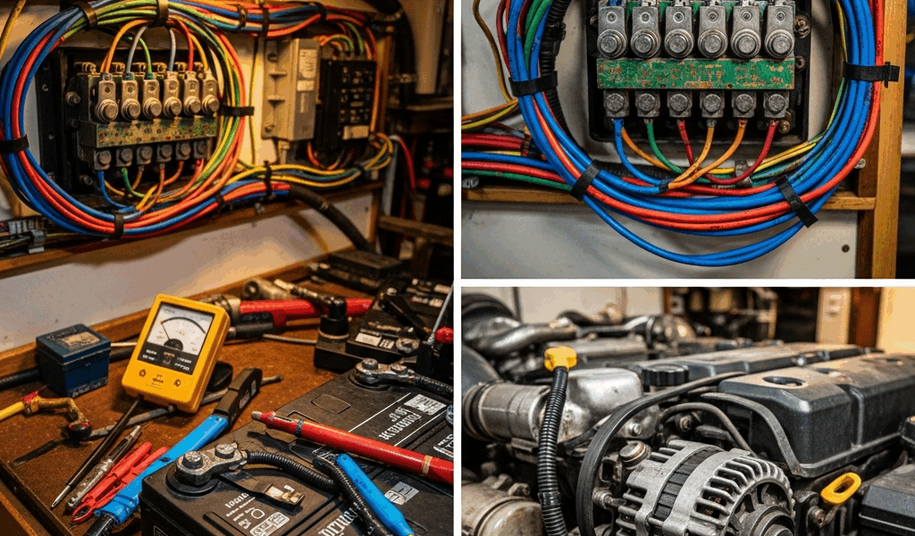
Corroded by salt air and diesel exhaust heat, my battery terminals had whitish-blue oxidation that looked harmless. It wasn’t. A simple multimeter test revealed 0.18V drop across the starboard battery terminal lug alone. Multiply that across a typical trawler’s electrical architecture — main battery terminal (0.18V), alternator positive lug (0.14V), battery-to-bus bar cable (0.08V), bus bar to inverter positive (0.06V). Six connections yielding six losses. Total voltage drop: 0.64V.
That 0.64V drop meant my alternator was operating 0.64V lower than actual battery voltage. A 14V alternator output became 13.36V at the battery. Charging suffers exponentially at this threshold. Performance collapse wasn’t sudden — it was cumulative and predictable once I understood the math.
Here’s the inspection protocol I developed:
First, visual exam under engine hatch lighting. Look for white, blue, or green powder on terminals and lugs. Touch them with a plastic swab — if material rubs off, corrosion is active. Note any cracked insulation or oxidized copper showing beneath coating.
Second, multimeter testing under load. Engine at idle, multimeter positive probe on alternator output terminal, negative probe on battery positive post. Record voltage. Now start heavy loads — turn on fridge compressor if it cycles, run inverter if possible. Voltage should drop less than 0.1V. Larger drops indicate terminal resistance.
Cleaning procedure specific to saltwater trawlers requires 400-grit sandpaper, not wire brushes (which compress corrosion rather than remove it). Disconnect battery negative. Remove each terminal. Sand until bare copper appears. Wipe clean. Coat with dielectric grease (Permatex MG Grease, $8 per tube). Reinstall terminal and tighten until snug — not cranked, just hand-tight plus quarter turn. Over-tightening deforms the lug post and increases resistance.
I replaced six critical connections during one oil change interval. Alternator output improved from 67 amps to 91 amps under load. That single maintenance session recovered 35 percent of my charging capacity. One afternoon of work. That margin became the difference between comfortable passages and anxious ones.
Real-Time Monitoring Strategies for Passage Makers
You can’t fix what you can’t measure. Before installing a battery monitor, I was guessing about charge state. “The voltmeter looks okay” isn’t diagnostic — it’s faith. That’s not a strategy.
A proper battery monitoring system reveals failure trends before catastrophe strikes. I installed a Victron SmartBattery monitor (BMV-712 model, $200) with the shunt permanently installed between battery negative and house ground. Now I see real-time amp-hour consumption, state of charge, time-to-depletion, and charging current simultaneously. That transparency changed everything.
Setup takes three hours if you’re methodical. The shunt is a precision resistor — 250A shunt for my system. It must carry all house current and nothing else. Battery negative connects to one shunt terminal, house ground and alternator negative connect to the other. Never parallel a shunt or you’ll invalidate its accuracy. The math demands precision here.
Using this data during passages became routine: every two hours I logged voltage, amperage, and state of charge. Within one week of logging I identified that my alternator output was declining by 5 amps every six-hour segment due to cooling fan cycling. That meant I had to reduce load proactively rather than reactively. Knowing this in advance meant making conscious choices instead of panicking at midnight.
Decision framework I adopted:
If alternator output drops 20 percent from first-hour output, reduce inverter load. Stop charging laptops and batteries. Run only essential navigation electronics.
If state of charge drops below 60 percent during a scheduled anchorage and alternator output remains below 70 amps, cut refrigerator cycling (raise temperature setpoint 2 degrees) or reduce anchorage duration by six hours.
If any single connection measures greater than 0.08V drop under load, schedule immediate cleaning.
A simple ammeter installed permanently on the alternator output cable ($40 for an inline panel meter) provides backup confirmation. Write down readings hourly. Trends emerge. Decline signals impending failure before it happens at night in fog when you’re vulnerable and exhausted.
Battery monitoring transformed my passage-making from reactive panic management to predictive planning. I no longer arrive at anchorages hoping my battery survived. I know exactly what margin I have. That knowledge is worth the investment in equipment and monitoring discipline.
“`




Stay in the loop
Get the latest passage maker mag updates delivered to your inbox.